Project Date: Dec. 8, 2017
Intro
As part of my Autonomous Mobile Robotics course, we had two main labs: one in which we had to Map and Localize within a certain area, and a second in which we had to path plan from a given start point to an end point.
Hardware Used
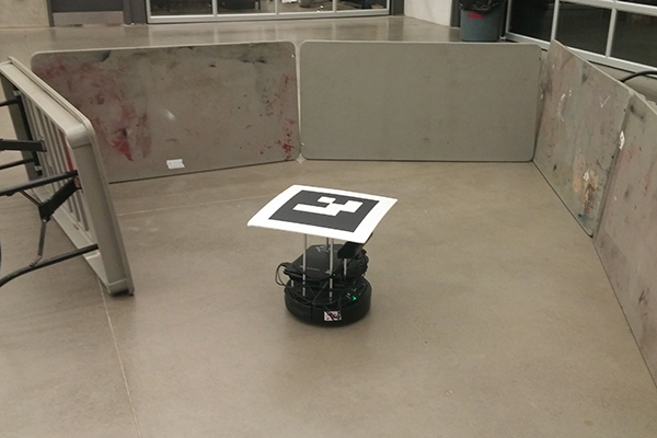
The hardware we used for these mini projects was a TurtleBot2 equipped with a XBOX 360 Kinect sensor, an AprilTag, and a HP netbook running Ubuntu 16.04.
In addition to the above, the workspace had a built-in indoor positioning system, which used FLIR BlackFly cameras to position the TurtleBots equipped with AprilTags.
Software Used
The following algorithms were developed in C++ for ROS Kinetic on Ubuntu 16.04. Additionally Gazebo was used to run the simulations to test the algorithms prior to the allotted lab slots.
My Role
During these projects, I worked on the implementation of the mapping algorithm, helped debug the particle filter used for localization, implemented the A* algorithm for path planning, and the obstacle padding feature used to maintain object distance when path planning.
Mapping
For mapping, a simple occupancy grid was used, which was filled using a row of the Kinect sensor data. To begin, a 200 x 200 matrix was initialized with p = 0.5. The p = 0.5 means that the occupancy of the elements is unknown and a 200 x 200 matrix was chosen due to having a 10 m x 10 m map with a resolution of 0.05 m. It should be noted that resolutions ranging from 0.01 m to 1 m were tested, but 0.05 m seemed to provide the best trade off between speed and quality of the resulting map. Next, the confidence in the sensor was placed as follows: p_free = 0.4, and p_occupied = 0.6. As it can be seen these values are very close to 0.5, meaning that there isn’t much confidence in the sensor and that it would have to register an area multiple time before the environments occupancy could be predicted with confidence. The updates were performed using an inverse sensor model, Bresenham’s line algorithm, and Bayes log odds update. It should also be noted that only data received within a timeframe of 100 us was used to perform one iteration of the update as it was found that otherwise the data received would be too out of sync, causing the map to mess up. Ideally, the robots motion model would be used to correct the data, but due to the low speeds experienced, this was thought to be unnecessary.
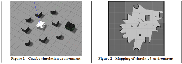
Testing mapping algorithm in simulation.
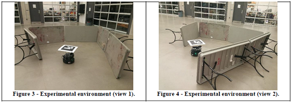
Mapping Environment – actual.
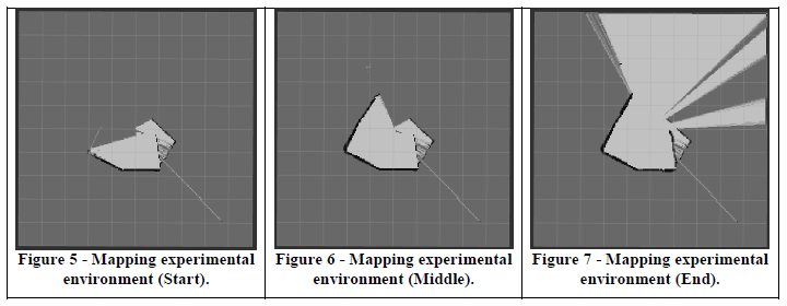
Result of mapping algorithm in actual environment.
Localization
For the localization of the robot, a particle filter was used. To begin, the motion and measurement models for the robot were defined. For this case, the motion model is the generic one for a 2D robot, where the control action is the commanded velocity and the angular rotation. In terms of the measurements, there are two sources: the IPS, and the odometer measurements from the robot. The particles were created by adding uniformly distributed noise to the predictions and the measurements. It was found that this performed well, so the noise profile was left unchanged even though it wasn’t the Gaussian noise we had seen in class.
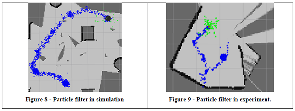
Localization using particle filter.
Path Planning
For the path planning aspect of this project, probabilistic roadmaps (PRM) were used. To begin, nodes are sampled randomly within a map, and only those not colliding with an obstacle are kept. Having sampled nodes, edges are added between nodes and their k-nearest nodes (again, only edges not resulting in a collision are kept). Once the nodes and edges had been sampled, the A* algorithm was used to find the shortest path from the start to end node. Euclidean distance was used as the heuristic distance. Several experiments were performed to see how different variables affected the performance of the PRM, such as trying various number of samples, changing how many neighbors a node connected to, and how wide the map padding was.

Path planning using PRM in simulation (blue lines represents selected path).
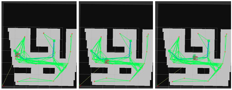
Path planning using PRM in actual environment (blue lines represents selected path).
Controls
As PRM was used for path planning, a very simple controller was used in which the TurtleBot was turned to a particular heading using a proportional controller and then TurtleBot was given a linear velocity allowing it to reach a destination point.
Credits
This series of projects was completed with my group members Dhruv Sharma and Suhaib Ishaque.
