Project Date: July 23, 2018
Intro
This project was created due to a personal need to allow all my family members to open and access the house through the garage. As such, I created this accessory for my garage door opener to allow all smartphones connected to the home’s WiFi network to be able to open and close the garage.
Hardware
The hardware consists of an Arduino Nano as the main control board, an ESP8266 ESP-01 development board as the WiFi transceiver, a BC846 transistor to trigger the garage door opener, and an MCP7940N real time clock. Additionally, an attempt was made to incorporate a microSD card, however the incorrect level shifter was used, so it currently doesn’t work (this will be fixed soon in the next iteration). As well, there is support for an SS49E hall effect sensor, however this was found to be overkill and will soon be replaced with a hall effect switch.
In the current iteration, the Arduino Nano is used due to its small size, ease of deployment, and access of libraries. In the future, the microcontroller (whether it is the ATMEGA328P or not) will be integrated directly onto the PCB. It should be noted that the ESP8266 ESP-01 was chosen for similar reasons.
The real time clock has been added to allow for additional functionality to be added such as checking if the garage is closed at night and if its not, to be able to notify the homeowners. Additionally, it will provide other timing related features, such as opening/closing the garage at a given time or to only do certain things including providing feedback at a given interval.
The microSD card slot was added to allow for easy WiFi setup, storage of other configurations, and to store the webpages needed (this takes up too much room on the microcontroller).
The PCB design was created using CircuitMaker and ordered from PCBWay.
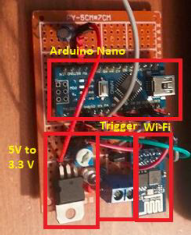
Prototype 1 for this project.
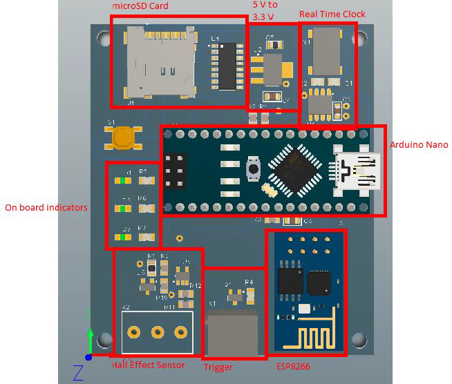
PCB version of the garage door opener.
Software
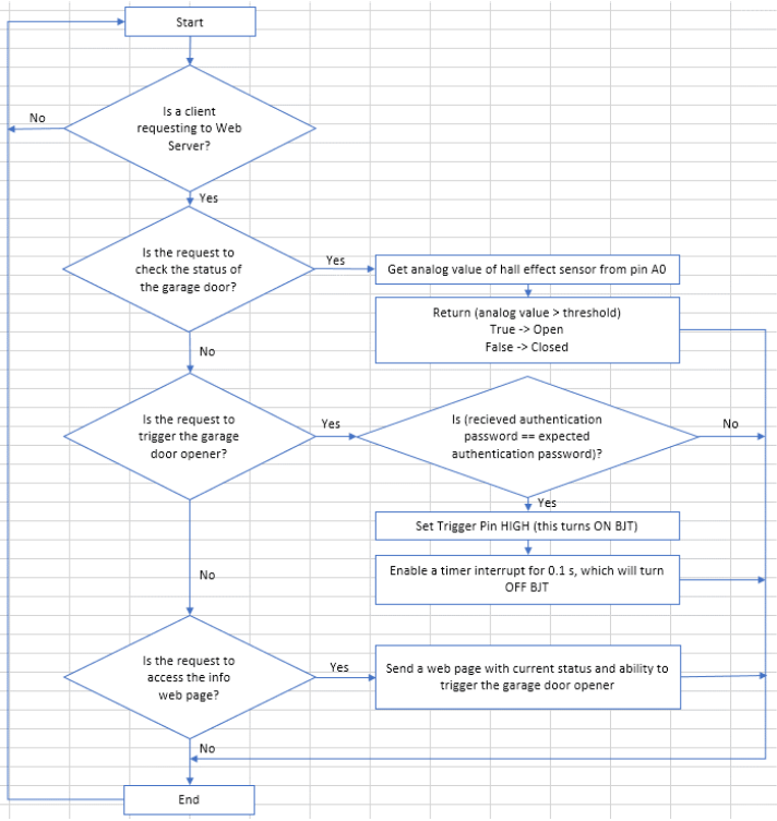
The software is best explained with the flowcharts, so take a look at the pictures below. As of right now, there is only an Android app, however I am working on an iOS app.
Setup flowchart for arduino.
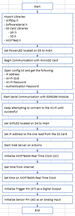
Flowchart of loop for arduino.
Case Design
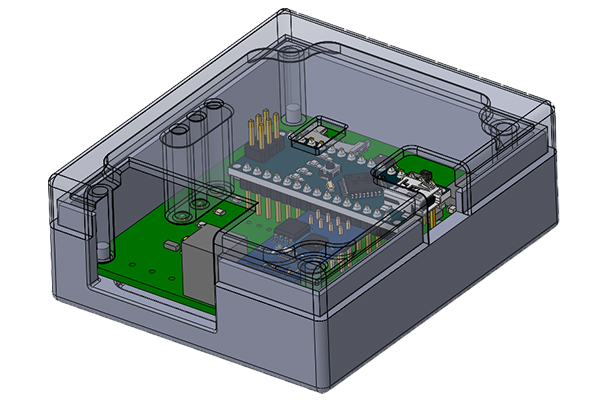
The case was designed using SolidWorks with the intention of 3D printing it on my Anet A8. See pictures for the design.
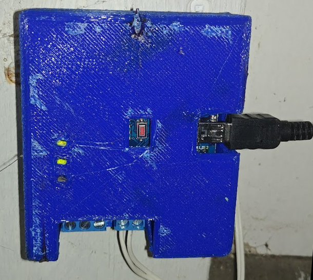
3D printed case with garage door opener PCB installed in my garage.
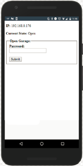
Current android app for the garage door opener.
Results and Discussion
This was a great project for me as I learned quite a bit as I had never done PCB design, WiFi development, and start to end product design prior to this. As such, I learned alot about the aforementioned topics. Overall, this project turned out well and is currently being used at my house. I am also planning on installing the other 4 PCBs I ordered at relative’s houses.
PS
If you are interested in this project and would like to install one at your home, make sure to contact me.
