Project Date: Nov. 23, 2017
Intro
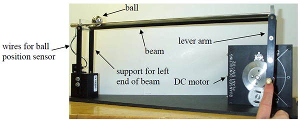
As part of our digital controls course, we were required to control a ball and beam apparatus moving the ball to follow a square wave. We were provided with overshoot, steady state error, settling time, and saturation requirements. We were also told to use the inner and outer loop control architecture taught in class. This allows the actuation layer, which is typically faster, to be tuned separately from the layer containing the variable of interest (in this case, this is the ball position). To prevent destruction of the apparatus, the plant was modeled in Simulink and MATLAB to allow testing of controllers prior to putting them on the physical apparatus.
My Role
My partner, Baraa, and I worked on this project together. We would brainstorm ideas together, implement code together (while one wrote the code, the other would review it to make sure there were no errors), and test on the ball and beam apparatus together.
Setup
The setup provided to us included the ball and beam apparatus, which was controlled using the National Instrument CompactRIO (cRIO), which contains a FPGA, a real-time processor, an ADC, and a DC servo motor drive and amplifier. The controllers were written using GWiz (a LabView application) and sent to the cRIO over ethernet.

Modelling the Motor System Plant
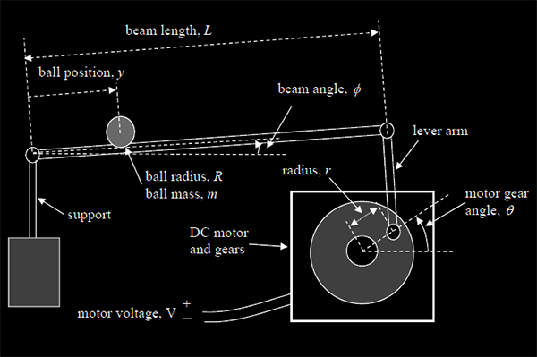
To begin, the motor system plant was stabilized, modeled, and validated. First, potentiometer voltage readings were converted to gear angle readings in radians by performing sensor scaling. This is an important step as it is important for a controller to be able to sense the variable it is controlling in the same units as the reference input. Additionally, the inverse of the sensor scaling provides a good start to create a model of the motor plant. To continue, static motor friction was accounted for and approximately cancelled out. This was done by first measuring the voltage required to barely get the motor moving under different scenarios. While this could have been crudely modeled by determining the two stiction values: one for CW movement, and one for CCW movement, Baraa and I decided to go one step further and create functions to define the stiction over the required range of +45 degrees to -45 degrees. In code, the stiction was accounted for by adding the additional voltage required to get the gear turning to the control signal. Having determined and modeled the former, the system model parameters were experimentally determined by analyzing the overshoot and time to first peak responses for the system under proportional controller. The overshoot and time to first peak analysis was done with various Kp gains to get accurate system parameters K1 and tau. Next, a saturator was implemented such that the gear angle output can only be within a certain safe operating range. This prevents the system from going into unwanted regions which could cause failure. Lastly, an overall block diagram was developed and analyzed.
Inner-Loop Controller Design
Having modeled and stabilized the motor plant, it was time to design the inner loop controller to meet the required specifications. This was done by first defining the “good” regions to place the additional poles in. Having defined the “good” region for the controller poles, many simulations were run to iteratively find poles that allowed the design requirements to be met. This was done by equating the actual characteristic polynomial with the desired characteristic polynomial, which allowed the continuous time controller to be determined. This controller was then discretized using a bi-linear discretization with a sampling period of 1.0 ms, which was determined by taking into a count that the sampling frequency should be atleast 25 times greater than the bandwidth of the system. Having the discretized controller, Simulink simulations were run to see if the overshoot and settling time criteria were being met. After several iterations, a controller was found that met the requirements in simulation. Having succeeded in the simulation, it was time to test on the actual plant. To ensure success, the simulation requirements had a safety factor of 1.25 on them.
Modelling the Ball and Beam
Having modeled and designed a controller for the motor system, it was time to divert our attention to the ball and beam system. The ball and beam system was modeled by finding a relation between the gear angle and the acceleration of the ball. The plant values K2 and K3 were found by looking at different angles (the acceleration should be the same in all cases) and taking the average of the 3 cases observed. It was found that K3 differed for the CW and the CCW direction.
Outer-Loop Controller Design
Finally, an outer-loop controller was implemented to control the ball position in the system. For the outer-loop controller, the inner-loop along with the actual plant all appear as the plant. First, a lead controller was implemented and analyzed both in simulation and in reality. This lead controller was provided by the course instructor as a starting point and it was found that the controller left a zero steady-state error. The steady-state error is not zero even though the plant has a sufficient number of integrators. This is because of non-linearities such as ball stiction in the system and the placement of these integrators. Having an integrator past all of the non-linearities in the plant is not as effective as an integrator at the beginning of the loop (ie. at the controller). This is because having an integrator at the controller level adjusts the output based on error between the reference and the output, while the integrator at the plant level is trying to adjust output based on error modified by the plant and its non-linearities. The mathematical closed loop system is able to stabilize because the Simulink model has linearized most of the non-linearities. Next, an outer-loop controller was designed using emulation design (pole placement). The same design method as outlined in “Inner-Loop Controller Design” was used. This outer-loop was tuned to meet certain specifications both in simulation and in reality. Lastly, ball-beam stiction that occurred when the gear angle was not large enough was modelled and accounted for. The anti-stiction block was designed by first determining at which gear angle the ball would start moving in the right and the left direction at various points on the beam. After collecting data at three points on the beam for the CW and CCW direction, a linear and quadratic fit was done on the collected data. This provided functions to counter act the stiction. After testing the two models, it was found that the quadratic model performed better than the latter and as such was used in the final design.
Results and Conclusions
Overall, this project as part of our digital controls course really gave us the opportunity to work with a real system and learn the process involved in developing controllers for a given system having been provided with minimal system parameters. It provided me with a good understanding of how to break down the system to allow me to focus on it piece by piece. In this particular problem, it would be very hard to model and control the system if we approached the problem directly without building the motor system controllers first. Additionally, it allowed me to further develop my skills in controls and using MATLAB and Simulink to iterate and simulate designs in a timely manner.
Credits
This project was completed with my group member Baraa Hamodi. You can find out more about him and his work on his website.
