Project Date: March 23, 2017
Intro
As part of our design workshop course, we were given a challenge in which we had to design and build a device that had to take a package from a starting location to its random destination on the other side of an approximately 1 m high wall. The wall structure had a metal section made of steel, a wooden section, and a section with a ramp up and down.
Our Approach and Implementation
Originally, we wanted to create a robot that would drive up to the wall, grab the top using a claw, rotate over (almost like a ferris wheel), unhook, and then drive to the destination. However, after doing some prototyping with laser cut acrylic and wood, it was found it would not be feasible in the given time frame of 2.5 months.
As such, it was decided a month into the project to switch to a car with a magnetic base, which would allow it to drive up the metal section of the wall.
Mechanical Design
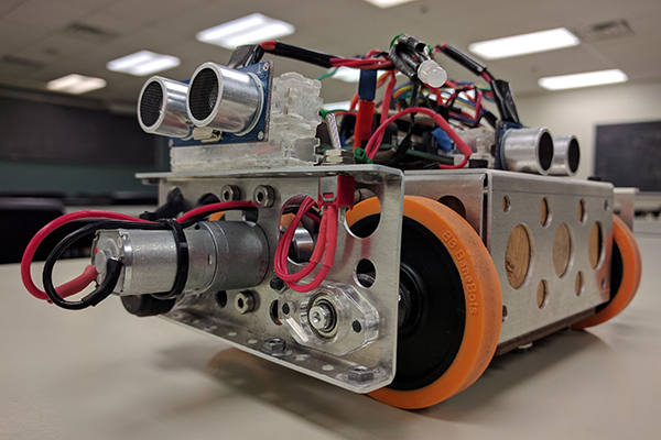
The mechanical design consists of 4-wheeled tank drive car with magnets placed at the bottom. The geometry of the chassis was mainly determined by the geometry of the metal section of the wall, the size of the electronics, and the size and location of the powertrain components. Additionally, to determine the magnet locations and configurations, real world experiments in addition to ANSYS AIM simulations were conducted.

Testing chassis dimensions in CAD to ensure car can travel over metal structure.
In terms of the geometry of the metal section, it had to be confirmed that the chassis would not interfere with the 5 different transitions that needed to happen. This meant that the ride height need to high enough to clear the triangular peak at the top, and the wheels needed to be peaking out of the chassis at the front and the back to be able to grip on and off the wall.
For the powertrain, each side consists of a Pololu 20D 63:1 Metal Gearmotor, which delivers power to the front and rear wheels through Gates GT2 profile, 6mm width belts. The gear ratio of the motor was chosen based on calculations done for the static and dynamic cases for travel on both flat and vertical surfaces. Belts were chosen due to their superior power transfer when compared to chains and gears.
To determine the magnet configuration, the approach taken involved first determining how well ANSYS simulated the real world forces created my the magnets, and once the comparison had been done, various configurations were studied to find the optimal one for the car. This was done by first studying the force created between a neodymium magnet and the steel wall using a force gauge. A plot of force vs. distance was created and compared to an ANSYS simulation of a similar model. The distance in real life was varied using a screw and the distance was calculated using number of turns and pitch of the magnet. Having determined the relation between simulation and real life, the safety factors could be chosen to ensure that the magnets would work once designed in simulation. As such, a simulation was run for various magnet configurations and the one with the best results was chosen. A Halbach array configuration was also considered, but it surprisingly didn’t perform as expected in simulation and the assembly would be difficult, so it was not selected.
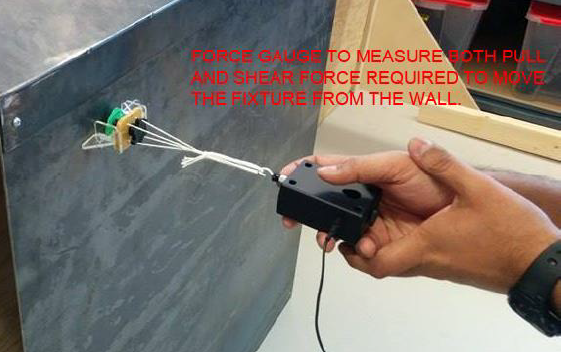
Testing actual magnetic force at various distances to correlate ANSYS model.
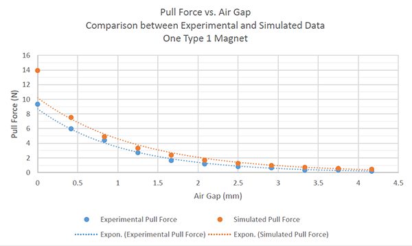
Experimental magnetic force data compared to simulation results.
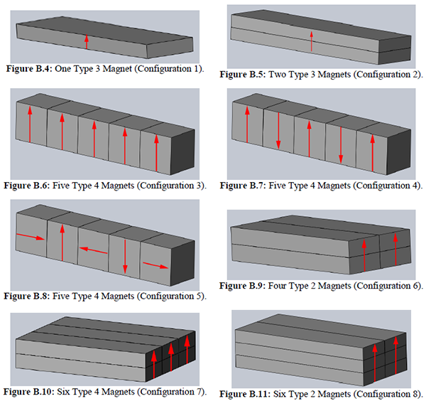
Different magnet configurations simulated in ANSYS.
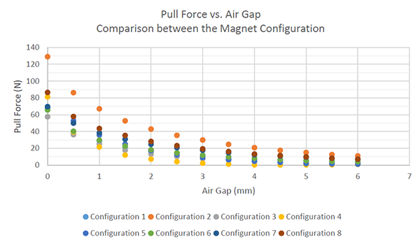
Simulated force results for the different magnet configurations.
Electrical Design
The electrical design for this robot was fairly simple consisting of an Arduino Mega 2560 as the main compute board, a dual-channel motor driver, two HC-SR04 ultrasonic sensors, one IMU, and two encoders. This was all powered through a two cell LiPo battery with a capacity of 1500 mAh.
Originally, it was intended to have a 25 W buck boost convertor between the battery and the rest of the components to ensure their was no voltage drop, however, the component fried and it was decided that the motor voltages could be compensated in software.
Software Implemenation
For the software, a state machine was setup to allow the robot to do different things as it reached a different part of the course. For example, the code to drive on a flat surface and a vertical surface are slightly different and the goals between the different stages also differ.
A few things our software was really good at was 90 degree turns and finding and going to the final destination. The 90 degree turns were almost flawless as Hammad had written a custom IMU library delivering data with negligible noise and because Shubham and I had spent time to tune the PID to achieve 90 degree turns well. Another factor that helped was the tuning that was performed to balance the two sides of the tank drive. In terms of the code that found and drove to the final destination, it performed well due to the simplicity of the algorithm. It was determined that the car would get of parallel to the left side wall, which meant that if the car drove straight, any variance in the right ultrasonic sensor would be due to the pole at the final destination. Because the car was able to turn well, it would be able to turn and drive straight till it noticed a change in IMU pitch as the final destination was a platform on the floor.
My Role
My role in this project was to design the magnet array, help with mechanical manufacturing and assembly, and help with electrical design and assembly. In addition, I wrote and tuned the PID control loop for making 90 degree turns.
Problems Faced
A multitude of problems were faced throughout the duration of this project. To begin, the switch from the original concept to the final design happened 1 month in, meaning that the project had to be executed on a shortened timeframe of 1.5 months. This meant that timeframes of activities such as designing, manufacturing, and testing had to be shortened. For example, majority of the design was done over a week, with little time to prototype or review, meaning that the final chassis was a bit smaller then expected. This caused troubles in fitting in the electronics and was dealt with by flipping the wheel assemblies outwards such that the motor was sticking out. To continue, another issue faced by the team was that the designed magnet holders would not allow the magnet to be close enough during the transition from the vertical section to the angled section of the wall. This caused the car to lose contact and fall off. Over time 4 iterations of the magnet holders were done and at one point it was working pretty well, however the car got heavier due to additional wiring requirements, causing the car to not work at that section. Furthermore, the motor shaft was 1 mm smaller than the pulley’s hole diameter. While this was not originally thought of as an issue as some of the group members had solved a similar issue using tape as filler in the past, this time this was not the case due to the rpm and torques experience. This problem was solved by lathing an aluminum sleeve to fill the gap. Another issue faced in the same area was that “Dollarama” super glue was used to hold the sleeve onto the shaft. This was a poor choice as the shaft would come loose from the sleeve leading to loss in performance. This was fixed by using proper two compound adhesive. Other problems faced were in the service department. Whenever any component broke in the powertrain, it would take a good 2-3 hours to dismantle the assembly to remove the component, replace it, and reassemble the powertrain. Similar issues were faced when replacing the battery as it was located at the bottom of the chassis and the easiest way to access it was to remove the magnet holders.
Results and Conclusion
Overall, while the car had issues getting over one aspect of the wall, it performed reasonably in all other sections. Additionally, I learned alot about designing and executing a mechatronics system with a team of engineers.
Credits
This project was completed with my group members Shubham Aggarwal, Baraa Hamodi, Hammad Mirza, and Dhruv Sharma.
